
OPTICAL KILL SWITCH
DESCRIPTION |
|
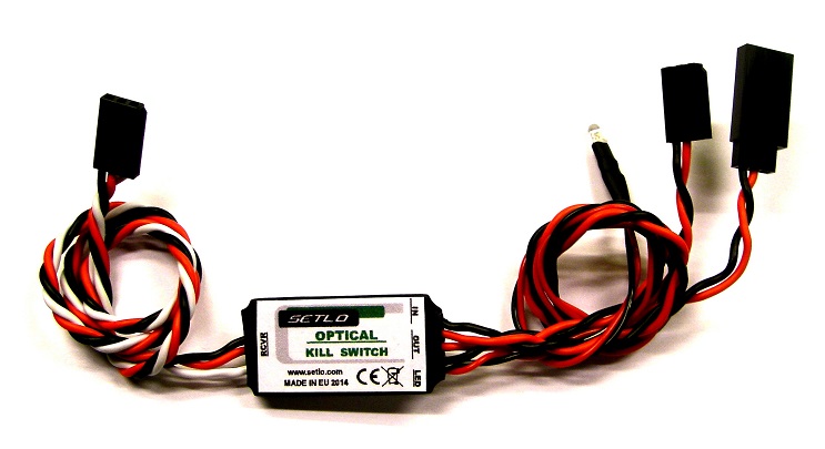
Designed specifically for large RC models powered by gasoline engines with electronic spark ignition. Its main task is to give the possibility to shutdown the gas engine from RC Transmitter and also to separate receiver circuits with RC accessories from the circuit powering the ignition unit, which may cause strong electromagnetic noise, and as a result loss of control. Considerably reduces the possibility of RC range loss. Simultaneously, giving the possibility to emergency turn off the engine in a few ways. - Double opto-isolated transmission controlling ignition unit (ON-OFF) Total resistance to electromagnetic interference induced in the ignition by separating circuits by two optocouplers - Function of switching ON and OFF the ignition directly from RC transmitter Applied to switch off the engine also in case of throttle servo failure. - Switching sequence protection When the ignition cutoff switch at TX is in “ON” position during preparation and powering up the model, the ignition WON’T TURN ON! This prevents unexpected starting the engine. In order to turn on the ignition you must at first place TX cutoff switch into the OFF position and then “ON” (operating similar as in the electric motors controllers). In that case the LED diode will blink rapidly. - High quality wires Receiver, ignition and battery connection wires are all high quality 22AWG gauge. - Fail-Safe function Possible to setup a Fail-Safe function. In case of the communication lack with model for longer than 1 second the kill switch will turn off the engine and the LED diode will blink from now on until reset. of throttle servo failure. - Wide range of power supply voltage OPTICAL KILL SWITCH works correctly with 3.0 – 24.0 V on the RC receiver side, and 3.0 – 20.0 V on the ignition battery side. Maximum current consumption allowed is 5.0 A constant and 16.0 A temporarily. - No need to use additional mechanical switch Battery drain current when device is OFF is ONLY! 1,8uA (micro Ampere) at 6,0 V battery. And 20,0 uA at 16,V. It means that 2000mAh, 6V battery will drain out to zero for 126 years! 1,8uA drain current is much less than battery self discharge ratio. - Possiblity to power ignition module from receiver battery. By default the device is using power from receiver for system logic and from independent battery to power the ignition module. Those circuits are double opto-isolated from each other. However it is possible to power the ignition module also from receiver, without using extra battery. To do so it it necessarily to remove heat shrink tube and solder together two pairs of pads (right side at the photo). From now the battery input wire is not being used. Clearly visible diode indicates whether the ignition unit is turned off or on. Additionally the LED performs an important signaling role in case of stopping the engine by interference and transition into the Fail-Safe mode, or problems with the electrical installation. During disruption for longer than 1 second, the device is switched into the third operating status (Fail-Safe) causing switching the engine off and start blinking of diode. Diode will still blink also after the end of disruption. That means also after landing. In this way LED informs from what reasons the engine stopped in the air. Change of TX cutoff switch position also doesn’t erase the error of blinking diode. In order to reset Fail-Safe signaling (blinking) you must turn off and again turn on the receiver power with the main power switch. - Disabling the LED blinking F-S indication This function can be disabled by soldering pair of pads (left side at the photo). From now there will be only active ON and OFF function. The engine will be shut down in the case of: - Range loss for longer than 1 second (LED blinks). Less than 1 sec. will not perform any action - Faulty power supply of the RC receiver (breaks with the power supply or its lack) - Turning OFF the engine by using TX system |
|
LED diode status modes:
|